◆Technical parameter
■Electric
parameter
a. Conforms to standards: .2
b. Rated voltage (Ue): 230/400V; 50/60Hz
c.
Rated breaking capacity Icn: 6kA
d. DC short
circuit breaking capacity: maximum 60V/1 pole
25kA
e. Rated current In: 50, 63, 80, 100,
125A
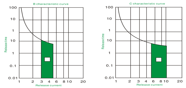
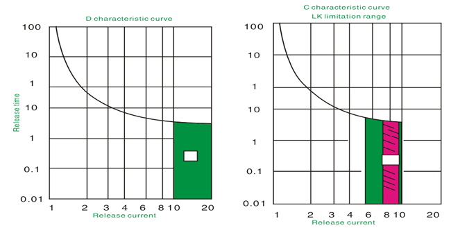
e. Trip characteristic: C, D
characteristic curve
f. Maximum connecting
fuse: 200A gL (>20kA)
g. Selectivity level:
3
h. Working ambient temperature:
-5℃~+40℃
i. Case protection level: (after
installation)
j. Life: more than 8000 times of
on-off operation
■Machinery parameter
a. Exposed face
length: 45mm
b. Case height: 90mm
c. Case width: 27mm each pole (1
pole)
d. Installation mode: use IEC standard
guide 35mm
e. Terminal mode: lifting
connecting terminal
f. Terminal
connecting capacity: 2.5-50mm2
■Main characteristic
a. High breaking
capacity and current limiting characteristic
b. Contactor mode indicator
c. Special
accessory series
◆Outline size

| Used in commerce and
civil circuit for short circuit and over load protection. |
Rated current In (A) |
Rated breaking capacity Lcn
(kA) |
1.5 modulus   |
3 modulus   |
C characteristic
curve
■Transient behavior 5~10In
■Mainly used for
commerce and civil building
distribution protection. |
20 |
25 |
M-LH-100/20/1/C |
M-LH-100/20/2/C |
| 25 |
25 |
M-LH-100/25/1/C |
M-LH-100/25/2/C |
| 32 |
25 |
M-LH-100/32/1/C |
M-LH-100/32/2/C |
| 40 |
25 |
M-LH-100/40/1/C |
M-LH-100/40/2/C |
| 50 |
25 |
M-LH-100/50/1/C |
M-LH-100/50/2/C |
| 63 |
25 |
M-LH-100/63/1/C |
M-LH-100/63/2/C |
| 80 |
20 |
M-LH-100/80/1/C |
M-LH-100/80/2/C |
| 100 |
20 |
M-LH-100/100/1/C |
M-LH-100/100/2/C |
| 125 |
15 |
M-LH-100/125/1/C |
M-LH-100/125/2/C |
D characteristic
curve
■Transient behavior 5~10In
■Mainly used in
industry power distribution field. |
50 |
25 |
M-LH-100/50/1/D |
M-LH-100/50/2/D |
| 63 |
25 |
M-LH-100/63/1/D |
M-LH-100/63/2/D |
| 80 |
20 |
M-LH-100/80/1/D |
M-LH-100/80/2/D |
| 100 |
15 |
M-LH-100/100/1/D |
M-LH-100/100/2/D |
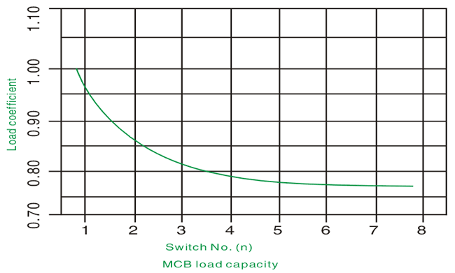
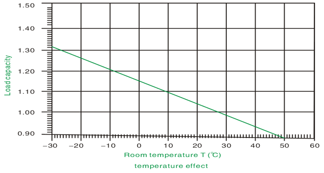
◆ Load
capacity
■For 1 pole M-LH series
■In temperature T (℃) and n
switches working state allowed load: IDL=LnKT(T)KN(N)
| Used in commerce and
civil circuit for short circuit and over load protection. |
Rated current In (A) |
Rated breaking capacity Lcn
(kA) |
4.5 modulus
 
3
pole |
6 modulus
 
4
pole |
C characteristic
curve
■Transient behavior 5~10In
■Mainly used for
commerce
and civil building distribution
protection. |
20 |
25 |
M-LH-100/20/3/C |
M-LH-100/20/4/C |
| 25 |
25 |
M-LH-100/25/3/C |
M-LH-100/25/4/C |
| 32 |
25 |
M-LH-100/32/3/C |
M-LH-100/32/4/C |
| 40 |
25 |
M-LH-100/40/3/C |
M-LH-100/40/4/C |
| 50 |
25 |
M-LH-100/50/3/C |
M-LH-100/50/4/C |
| 63 |
25 |
M-LH-100/63/3/C |
M-LH-100/63/4/C |
| 80 |
20 |
M-LH-100/80/3/C |
M-LH-100/80/4/C |
| 100 |
20 |
M-LH-100/100/3/C |
M-LH-100/100/4/C |
| 125 |
15 |
M-LH-100/125/3/C |
M-LH-100/125/4/C |
D characteristic
curve
■Transient behavior 5~10In
■Mainly used in
industry power distribution field. |
50 |
25 |
M-LH-100/50/3/D |
M-LH-100/50/4/D |
| 63 |
25 |
M-LH-100/63/3/D |
M-LH-100/63/4/D |
| 80 |
20 |
M-LH-100/80/3/D |
M-LH-100/80/4/D |
| 100 |
15 |
M-LH-100/100/3/D |
M-LH-100/100/4/D |
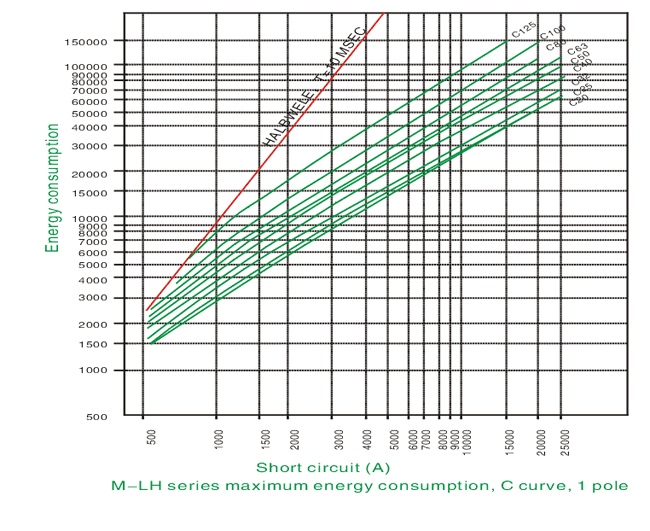
◆ Energy
consumption
Conforms to standards of

■M-LH (20-100) and fuse D0 or NH short circuit breaking
capacity
■ 1.4 high selectivity can be more than 1.4kA: □no
selectivity function
Fuse wire D01, D02, D03
selectivity
| M-LH rated current |
Fuse wire gL rated current (A) |
|
25 |
35 |
50 |
63 |
80 |
100 |
| C characteristic curve |
20 |
<0.5 |
1.0 |
2.0 |
2.9 |
3.9 |
7.6 |
|
25 |
|
1.0 |
1.9 |
2.8 |
38 |
7.6 |
|
32 |
|
1.0 |
1.8 |
2.7 |
3.6 |
7.0 |
|
40 |
|
|
1.6 |
2.2 |
3.0 |
5.6 |
|
50 |
|
|
|
2.1 |
2.8 |
5.2 |
|
63 |
|
|
|
|
2.7 |
4.8 |
|
80 |
|
|
|
|
|
4.3 |
|
100 |
|
|
|
|
|
|
|
125 |
|
|
|
|
|
|
| D
characteristic curve |
20 |
<0.5 |
0.9 |
1.7 |
2.5 |
3.4 |
6.7 |
|
25 |
|
0.9 |
1.6 |
2.3 |
3.2 |
6.2 |
|
32 |
|
0.9 |
1.5 |
2.3 |
3.0 |
6.0 |
|
40 |
|
|
1.4 |
2.0 |
2.6 |
4.7 |
|
50 |
|
|
|
1.8 |
2.3 |
4.3 |
|
63 |
|
|
|
|
2.1 |
3.7 |
|
80 |
|
|
|
|
|
3.1 |
|
100 |
|
|
|
|
|
|
Fuse wire NH-00
selectivity
| M-LH rated current |
Fuse wire gL rated current (A) |
|
25 |
35 |
40 |
50 |
63 |
80 |
100 |
125 |
160 |
200 |
| C characteristic curve |
20 |
<0.5 |
1.0 |
1.3 |
1.9 |
2.7 |
3.7 |
6.7 |
17.0 |
25.0 |
25.0 |
|
25 |
|
0.9 |
1.3 |
1.8 |
2.6 |
3.5 |
6.5 |
17.0 |
25.0 |
25.0 |
|
32 |
|
0.9 |
1.2 |
1.7 |
2.4 |
3.3 |
6.0 |
15.0 |
23.0 |
25.0 |
|
40 |
|
|
|
1.4 |
2.1 |
2.9 |
4.8 |
12.0 |
18.0 |
25.0 |
|
50 |
|
|
|
|
1.9 |
2.7 |
4.5 |
11.0 |
17.0 |
25.0 |
|
63 |
|
|
|
|
|
|
4.2 |
10.0 |
15.0 |
25.0 |
|
80 |
|
|
|
|
|
|
3.8 |
8.5 |
12.0 |
25.0 |
|
100 |
|
|
|
|
|
|
|
7.0 |
10.0 |
25.0 |
|
125 |
|
|
|
|
|
|
|
|
|
25.0 |
| D
characteristic curve |
20 |
<0.5 |
0.8 |
1.1 |
1.5 |
2.3 |
3.1 |
5.6 |
|
16.0 |
25.0 |
25.0 |
|
25 |
|
0.7 |
1.0 |
1.4 |
2.1 |
3.0 |
5.3 |
|
14.0 |
23.0 |
25.0 |
|
32 |
|
0.7 |
1.0 |
1.3 |
2.1 |
2.9 |
5.0 |
|
13.0 |
22.0 |
25.0 |
|
40 |
|
|
|
1.1 |
1.8 |
2.5 |
4.2 |
|
10.0 |
15.0 |
25.0 |
|
50 |
|
|
|
|
1.6 |
2.36 |
3.8 |
|
8.5 |
13.0 |
22.0 |
|
63 |
|
|
|
|
|
2.1 |
3.2 |
|
7.0 |
10.5 |
18.0 |
|
80 |
|
|
|
|
|
|
2.8 |
|
5.5 |
804 |
15.0 |
|
100 |
|
|
|
|
|
|
|
|
4.8 |
7.5 |
12.5 |
■Trip characteristic conforms to standards of
()
■B characteristic curve: used in lighting
distribution systems
■C characteristic curve: used in lighting
distribution, socket circuit or some
power
distribution systems
■D characteristic curve: used in power or
other high inductive load circuit.
